DIY EMF Detector: Can You Make One?
You can create a DIY EMF detector using an Arduino microcontroller paired with basic electronic components like operational amplifiers (e.g., LM358) for signal amplification and sensors for magnetic field detection. Incorporate a piezo buzzer for audio feedback and an LED for visual alerts, ensuring accuracy through calibration with known field sources.
Power the device with fresh batteries and apply troubleshooting techniques to maintain its functionality. Continue exploring for more detailed steps and applications.
Disclaimer: As an affiliate, I may collect a share of sales from the links on this page.
Understanding EMF and Its Importance

When examining electromotive force (EMF) and its significance, it’s essential to recognize that EMF represents the energy transfer in an electric circuit.
Measured in volts, EMF indicates energy per unit charge. It converts various energy forms, like chemical in batteries, into electric energy. EMF can also be generated by time-varying magnetic fields, which are one of the sources of electromagnetic radiation.
The key equation, (varepsilon = frac{u}{q}), shows the relationship between energy and charge. EMF is a scalar quantity, meaning it has magnitude but no direction.
Importantly, EMF differs from potential difference; it measures total energy available per charge, not the voltage drop across components. Understanding this distinction is fundamental in electrical engineering and circuit design. Additionally, EMF can arise from various sources such as chemical reactions and time-varying magnetic fields.
Essential Components for Your EMF Detector
Building an effective EMF detector requires an assortment of essential components that work together to accurately sense and interpret electromagnetic fields.
Key Components
Operational amplifiers, like the LM358, amplify weak signals. Inductors and coils sense magnetic fields, while dynamic sensors translate them into modulated signals. A dual operational amplifier circuit, such as the LM358, is essential for enhancing the sensitivity of your EMF detector.
Circuit boards maintain structural integrity and facilitate connections. Power sources, either batteries or external supplies, energize the circuitry.
Sensors
Electric field sensors detect changes caused by various devices. Magnetic field sensors measure fluctuations in magnetic fields.
Tri-axis and broadband sensors provide extensive data across multiple frequencies. Together, these components enhance the accuracy and functionality of your EMF detector.
Step-by-Step Guide to Building Your Detector
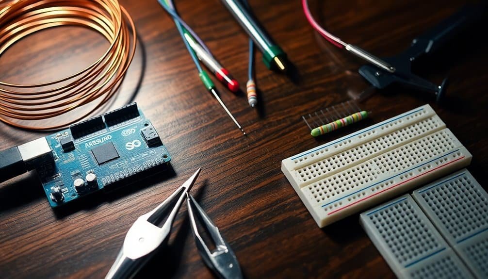
To create your EMF detector, follow this systematic approach that outlines the necessary steps and components involved.
Start with an Arduino microcontroller for customization; it’s user-friendly and requires minimal parts. This allows for flexibility in adapting to different EMF radiation levels in various environments.
Gather a simple antenna, like a piece of wire, for electromagnetic field detection.
Integrate a piezo buzzer for audio feedback, similar to a Geiger counter.
Include an LED indicator to provide visual cues when it detects fields.
Optionally, incorporate potentiometers to adjust sensitivity for various environments.
Finally, design a safe and ergonomic housing for your device to guarantee durability and ease of use while monitoring EMF levels effectively. This project can be adapted to create an EMF detector, allowing for further exploration and customization as you gain experience.
Soldering and Circuit Assembly Techniques
Soldering and circuit assembly form the backbone of your DIY EMF detector project. To guarantee success, follow these essential techniques:
- Use Proper Tools: Always have a good soldering iron, tip cleaner, and safety glasses on hand.
- Component Placement: Strategically position parts for ideal heat dissipation and signal integrity.
- Keep Workspace Clean: Maintain a tidy area to prevent contamination and errors during assembly.
Additionally, apply flux to improve solder flow.
Handle static-sensitive components with care, grounding yourself when necessary.
Verify component values with a multimeter before soldering, and conduct final inspections for shorts or open circuits to guarantee a reliable build.
Programming Your Arduino for EMF Detection
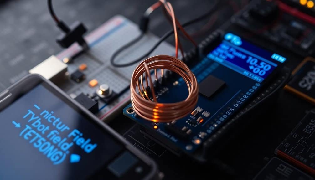
Programming your Arduino for EMF detection involves a structured approach to guarantee accurate readings and effective data interpretation.
Start by using the Arduino IDE for coding. Utilize analog pins to read EMF signals collected by antennas or probes. Set thresholds in your code to identify significant EMF variations, and implement noise reduction techniques to enhance accuracy. Additionally, ensure you are aware of the types of EMF radiation you aim to detect, as this knowledge can aid in calibrating your device effectively.
Ground your Arduino in a metal enclosure to minimize self-oscillation. Use Serial.print) to monitor readings for debugging purposes. You can also integrate digital pins for potential future feedback mechanisms.
This foundational coding prepares your device for reliable and precise EMF detection.
Visual and Audio Feedback Mechanisms
While detecting electromagnetic fields, integrating visual and audio feedback mechanisms enhances user experience and data interpretation.
Consider these components:
- LED Arrays: Ten LEDs can visually indicate the field strength, with colors possibly denoting different signal thresholds.
- Buzzer Output: Audio alerts vary in frequency based on strength, helping you quickly determine areas of concern.
- OLED Displays: These modern screens show numerical values and graphs, providing precise readings of field strength.
Using both feedback types enables faster data assessment and effective detection while accommodating diverse user preferences and operational contexts.
This combination gives a thorough view of electromagnetic field environments.
Testing and Calibrating Your Device
Testing and calibrating your DIY EMF detector guarantees it provides accurate and reliable measurements.
Begin by using known magnetic field sources, such as electric meters outside homes, for calibration. Measure at distances like 1 and 2 feet to confirm consistent results.
Adjust your device to maintain a 5-10% error rate, which is acceptable for home use. Utilize an unplugged microwave as a zero-field reference and RF generators to fine-tune sensitivity.
Collect data from multiple locations to test versatility. Finally, verify the device against known standards, confirming all sensor types—magnetic, electric, and RF—are accurately calibrated for precise readings.
Applications of DIY EMF Detectors
Understanding the various applications of DIY EMF detectors broadens their utility beyond mere hobbyist tools. Here are three main applications:
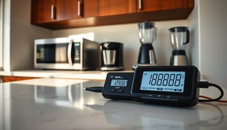
- Home Environment Monitoring: Detect electromagnetic fields from electronics like microwaves and routers. Map out areas with high EMF and assess energized appliances.
- Educational Demonstrations: Engage students with hands-on experiments illustrating EM fields generated by devices, enhancing their understanding of physics.
- Industrial and Workplace Safety: Survey workplaces for high EMF areas, ensuring compliance with safety standards while identifying machinery malfunctions and preventing equipment interference.
These applications underscore the versatility and essential roles of DIY EMF detectors in various fields.
Common Challenges and Troubleshooting Tips
When building a DIY EMF detector, you may encounter several challenges that can affect performance and accuracy. Component selection is critical; mismatched parts can lead to failure. Verify your Arduino board is correctly wired to the appropriate pins.
Ambient EMF from nearby devices can skew measurements, leading to false positives. Always calibrate your device at startup to establish a reliable baseline. Check solder joints for security, and use a breadboard for troubleshooting.
If using batteries, pay attention to voltage stability to avoid power drain. Monitor antenna positioning and implement shielding to minimize interference for accurate readings.
Frequently Asked Questions
Can I Use Other Microcontrollers Instead of Arduino for This Project?
Yes, you can use other microcontrollers like ESP32, Raspberry Pi, or STM32 for your project. Each offers unique features and compatibility, providing flexibility for your design and allowing you to tailor capabilities to your needs.
Is It Safe to Use EMF Detectors Near High-Voltage Equipment?
Using EMF detectors near high-voltage equipment isn’t always safe. You should practice caution, read instructions carefully, and test the device on known sources to guarantee accurate functioning and avoid potential hazards.
How Can I Improve the Accuracy of My EMF Readings?
Did you know that 85% of EMF measurements vary greatly with distance? To improve accuracy, calibrate your detector regularly, vary sensor positions, and analyze multiple readings to map the field effectively. Remember to minimize interference!
Are There Any Legal Considerations When Using EMF Detectors?
When using EMF detectors, you need to comply with FCC guidelines in the U.S. or the Electromagnetic Fields Directive in the EU. Make sure your readings are within legal exposure limits for safety and compliance.
Can I Modify My Detector to Measure Different Frequencies?
Sure, you can definitely modify your detector to measure different frequencies! By adjusting the code and using the analog-to-digital converter, you’ll transform voltage readings into various frequencies, enhancing your device’s responsiveness and functionality.
Conclusion
Creating your own EMF detector is a fulfilling project that merges creativity with technical skills. Careful assembly and calibration ensure accurate readings, allowing you to explore electromagnetic fields confidently.


